资源简介
实现两个超声波模块的数字通信,可接收多位字符和数字,发送端通过串口1连接电脑接收数据,接收端采用液晶显示,接收和发送模块通过串口通信,超声波模块的作用是代替杜邦线的连接,采用队列的形式接收和发送数据

代码片段和文件信息
//接收程序
#include “led.h“
#include “delay.h“
#include “sys.h“
#include “key.h“
#include “usart.h“
#include “Manchester.h“
#include “usart2-5.h“
#include “Commun.h“
#include “lcd.h“
extern u8 crc_check_flag;
extern u8 Secode_Data;
extern Secode_Queue Manchester_buff;
u8 Rec_Buff[100];
void GPIO_Init_c(void);
int main(void)
{
u8 i cnt old_cnt;
int x = 0 y = 75;
delay_init(); //延时函数初始化
LED_Init(); //初始化与LED连接的硬件接口
KEY_Init();
uart_init(115200);
USARTx_Configuration(115200);
LCD_Init();
LCD_Clear(BLUE);
POINT_COLOR = RED;
BACK_COLOR = WHITE;
// GPIO_Init_c();
Receive_Init(); //接收队列初始化
printf(“接收端\n“);
while(1)
{
LCD_ShowString(20 30 200 16 16 “data communication“);
LCD_ShowString(20 50 200 16 16 “Receive_data: “);
if (crc_check_flag)
{
cnt = Queue_Length(Manchester_buff);
for (i=0; i
Rec_Buff[i] = Queue_Out(&Manchester_buff);
printf(“%d “ Rec_Buff[i]);
LCD_ShowString(x + 8 * i y 200 16 16 &Rec_Buff[i]);
}
printf(“接收**************************成功\n“);
if (cnt < old_cnt)
{
for(i=cnt; i
LCD_ShowString(x + 8 * i y 200 16 16 “ “);
}
}
crc_check_flag = 0;
old_cnt = cnt;
}
// GPIO_SetBits(GPIOBGPIO_Pin_11);
// delay_ms(20);
// GPIO_ResetBits(GPIOBGPIO_Pin_11);
// delay_ms(20);
}
}
void GPIO_Init_c(void)
{
GPIO_InitTypeDef GPIO_InitStructure;
RCC_APB2PeriphClockCmd(RCC_APB2Periph_GPIOB ENABLE);
GPIO_InitStructure.GPIO_Pin = GPIO_Pin_11; //LED0-->PB.5 端口配置
GPIO_InitStructure.GPIO_Mode = GPIO_Mode_Out_PP; //推挽输出
GPIO_InitStructure.GPIO_Speed = GPIO_Speed_50MHz; //IO口速度为50MHz
GPIO_Init(GPIOB &GPIO_InitStructure); //根据设定参数初始化GPIOB.5
GPIO_SetBits(GPIOBGPIO_Pin_11);
}
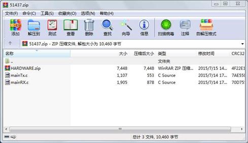
属性 大小 日期 时间 名称
----------- --------- ---------- ----- ----
文件 7448 2015-07-15 14:53 HARDWARE.zip
文件 1905 2015-07-14 17:22 mainRX.c
文件 1107 2015-07-14 17:21 mainTx.c
- 上一篇:stm32驱动si4463收发
- 下一篇:OSD字符显示实验,采用MAX7456
相关资源
- STM32f103超声波模块例程
- STM8S SX1278 项目和源代码
- STM32F103C8T6+NRF24l01无线通信
- 用于无线传感器网络应用的超声波传
- 基于ARM和GPRS的无线通信系统设计
- 基于ZigBee的车间环境监测系统的设计
- 基于Zigbee无线通信的井下人员定位系
- 短距离无线通信及组网技术162234
- 中国移动spn技术白皮书_wrapper
- 无线通信 美哥德史密斯 著
- 循迹小车51程序(超声波 颜色识别 舵
- 基于51单片机的超声波测距技术实现含
- 51单片机智能小车花式,寻迹,红外,
- YDT 3755-2020 基于LTE的车联网无线通信技
- 大话无线通信 361页 高清书签版 pdf
- 南邮 数字通信 课件
- 无线通信答案
- 基于M-BUS的矿用超声波明渠流量计设计
- 超声波遥控开关电路图
- 基于51单片机超声波测距毕业设计
- STM32F103RCT6 TIME4 TIME5 同时捕获六路
- HC-SR04超声波模块(包含基于51stm32配套
- <数字通信>第四版Proakis英文版 课后答
- STM32f103C8t6型单片机用于超声波测距
- 无线通信中的微波谐振器与滤波器
- 超声波车速测量系统设计
- 基于单片机控制和超声波传感器的液
- MOXA工业级无线通信应用指南.pdf
- 光纤无线通信系统中实现光载毫米波
- 光纤无线通信系统产生毫米波技术
 川公网安备 51152502000135号
评论
共有 条评论